Description
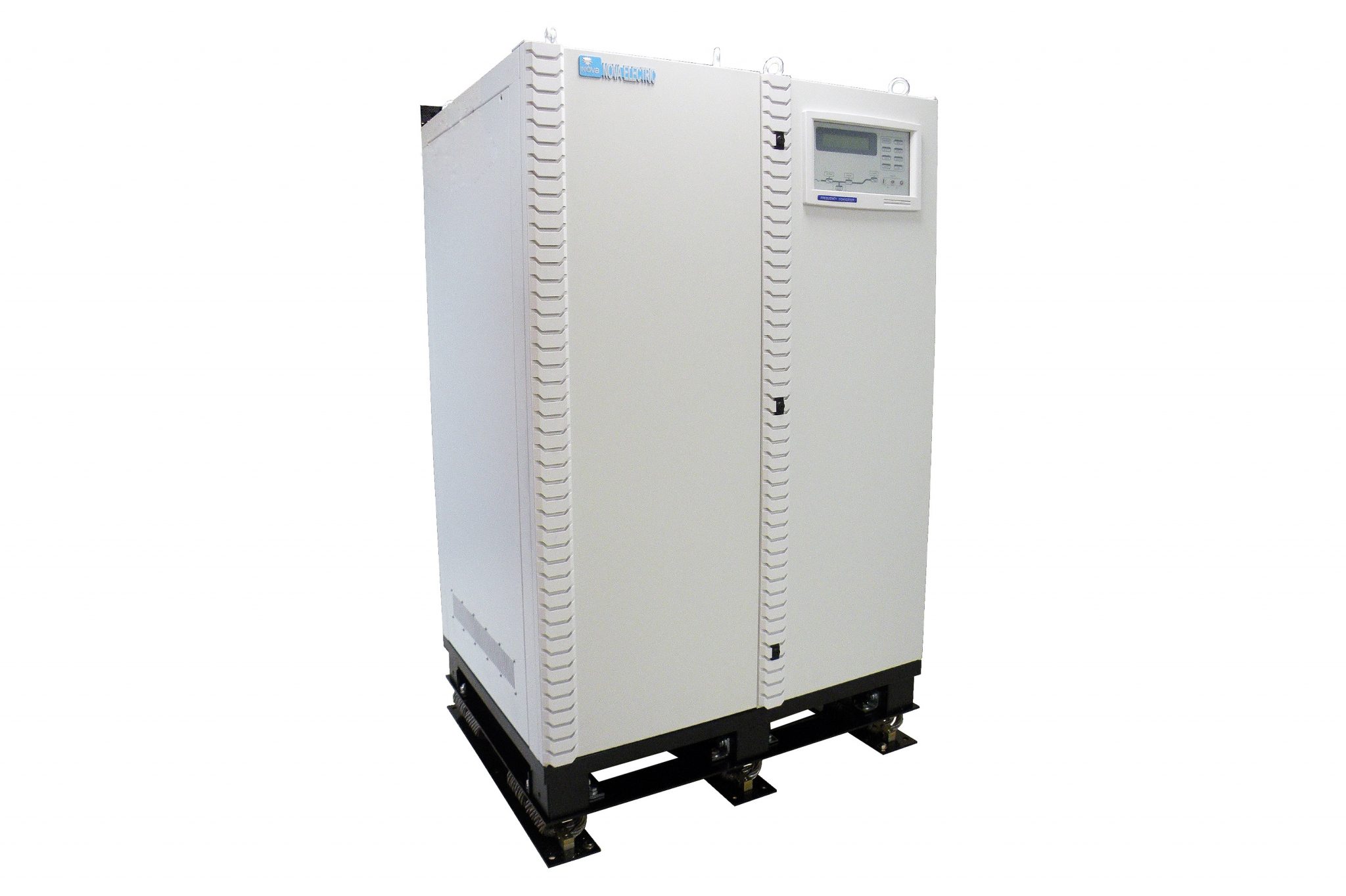
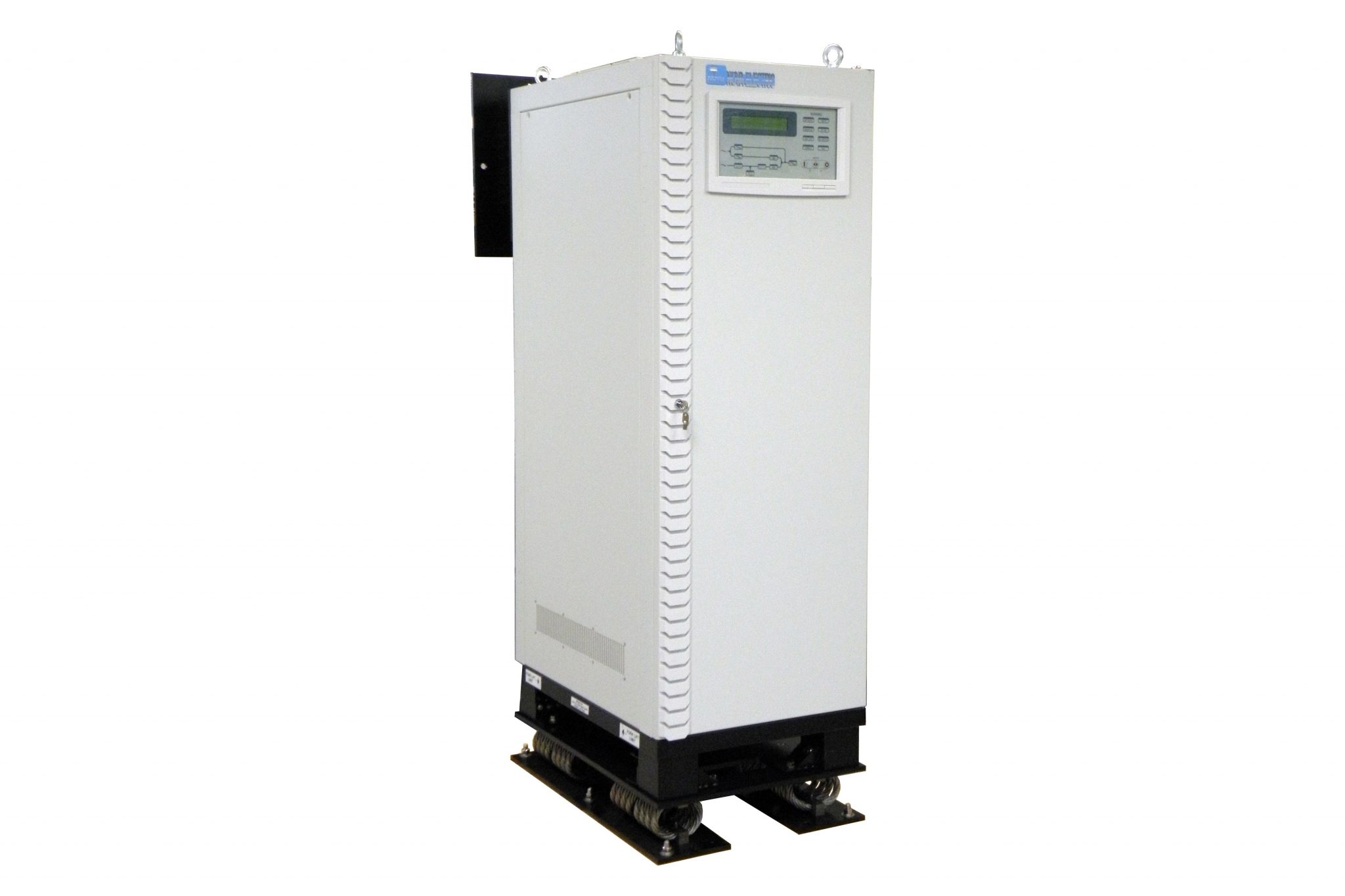
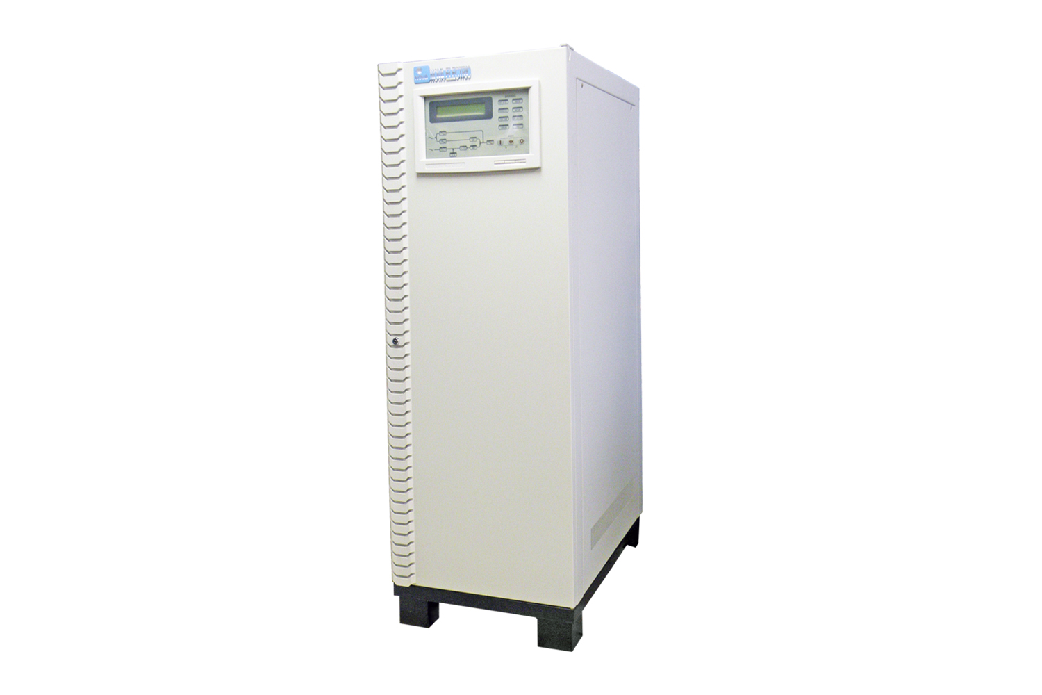
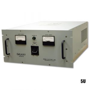
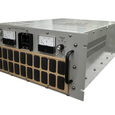
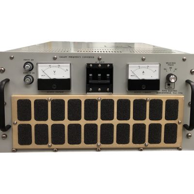
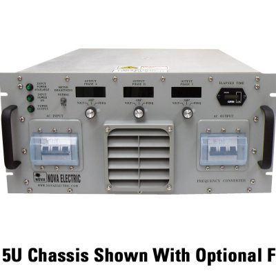
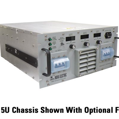
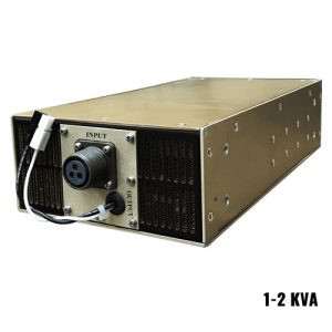
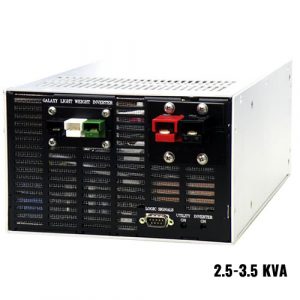
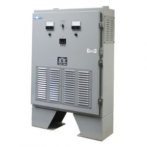
Nova’s Jupiter-Series Solid-State Frequency Converters are high-reliability power sources specifically designed for demanding commercial, heavy industrial, and military applications. They can be built to meet MIL-STD-810, MIL-S-901, MIL-STD-461, and other standards optionally. These models utilize state of the art technology and the most durable components, offering maximum field-proven reliability for severe environment and high reliability applications. Single-phase input and/or output models are available upon request. Typical applications include:
- Military: HMMWV, UAV, Shipboard, Submarine, Aircraft and Mobile Power Units, Shelters
- Aircraft Power
- Communications Systems
- Cellular Sites
- European Power / Export Testing
- Power Conditioning & Frequency Stabilization
- U.S. Power Abroad
- Railroad Signaling Power – 25, 91.66, 100, 200, and 250 Hz. available
Specifications
Specifications for the Nova Jupiter Frequency Converter
| 3-Phase Input/ 3-Phase Output |
| KVA |
10 |
20 |
30 |
40 |
50 |
60 |
80 |
100 |
120 |
160 |
240 |
320 |
450 |
| AC INPUT |
|
| Input Voltage (VAC) |
Please Specify | 115/200 | 120/208 | 220/380 | 230/400 | 240/415 | 277/480 WYE
220 3 ph delta | 240 3 ph delta | 380 3 ph delta | 400 3 ph delta | 480 3 ph delta
Single Phase available optionally – consult factory for details |
| Input Range |
+/- 20% (>+20% is available upon request) |
| Input Frequency |
50/ 60 + 5Hz |
| Power Walk In |
0% – 100% :20 sec |
| Rectifier |
98% |
| Rectification Type |
6 Pulse Standard, 12 Pulse Optional |
12 Pulse Standard |
| Battery Start |
Yes, UPS can be started without AC source. |
| INVERTER (AC output) |
|
| Output Voltage (VAC) |
Please Specify | 115/200 | 120/208 | 220/380 | 230/400 | 240/415 | 277/480 WYE
220 3 ph delta | 240 3 ph delta | 380 3 ph delta | 400 3 ph delta | 480 3 ph delta
Single Phase available optionally – consult factory for details |
| Wave Form |
Sinewave |
| Output Power Factor |
0.7 lead to lag |
| Output Frequency (free running) |
50/60/400 Hz +/- 1Hz (crystal controlled) please specify |
| Phase Shift Under 100% Unbalanced Load |
<0.5% |
| THD (Linear Load) |
< 2% |
| Overload |
| <110% |
Continuous |
| 110-125% |
Up to 15 minutes |
| 125-150% |
Up to 10 minutes |
| >150% |
Up to 1 minute |
| Efficiency (100% Load) |
93% |
93% |
93% |
93.5% |
93.5% |
94% |
94.5% |
94.5% |
95% |
95% |
95% |
95% |
95% |
| Overall Characteristics |
| Overall Efficiency |
91% |
91% |
91% |
91.5% |
92% |
92% |
92.5% |
92.5% |
93% |
93% |
93% |
93% |
93% |
| Maximum Heat Dissipation (kw) |
0.7 |
1.4 |
1.9 |
2.6 |
3 |
3.5 |
4.6 |
5.4 |
6.5 |
8.7 |
13 |
17.4 |
25.2 |
| BTU/h @ Full Load |
2.4K |
4.8K |
6.5K |
8.9K |
10.3K |
12K |
16K |
19K |
22K |
30K |
45K |
60K |
86K |
| Audible Noise |
<65 dBA (at 1m) |
<67dBA (at 1m) |
| Temperature |
0-40ºC (32-104ºF) (Other ranges available) |
| Humidity |
0%-95% (Non-condensing) |
| Altitude |
<1500 m Above Sea Level |
| EN50091-1, -2 |
Yes |
| Short Circuit Protection |
Yes |
| MTBF |
As per MIL-HDBK-217:30,000 Hours
As per Field Experience >100,000 Hours for loss
of AC Output |
| Lightning / EMC Filter |
MOV / Input & Output ( FCC CLASS A) |
| Galvanic Isolation |
Input and Output True Galvanic Isolation |
| LED, LCD, Audible Alarm |
Yes |
| Remote Control and Communication Interface Choices |
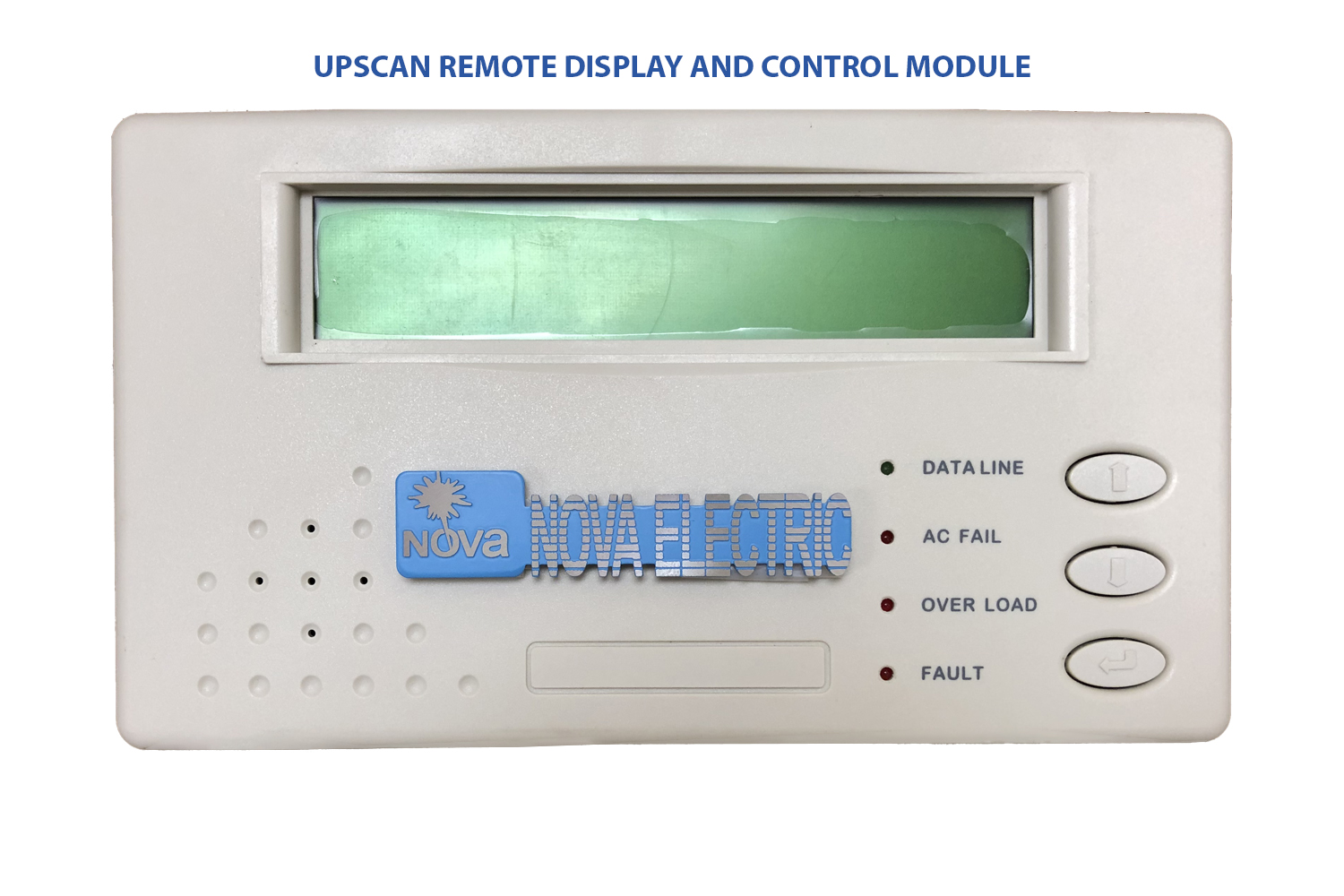
Dry Contact, RS-232, RS-485 (Optional,) UPScan Monitoring 1~99 Units Simultaneously (Optional,) Netagent (Optional,) MODBUS (Optional) |
MONITORING FEATURES
- The unit includes an RS232 communication option called UPSCOM which can monitor the output parameters and any abnormal conditions that have occurred in real time.
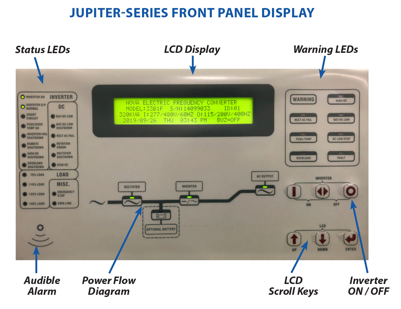
FRONT PANEL LCD DISPLAY AND LED INDICATORS
- This will report all parameters including input and output voltages, currents, frequency, battery voltage, battery current, and many other functions.
LCD DISPLAY
- Real time status, data, and historical events are displayed via the LCD display. The FC parameters, real-time clock, inverter, and buzzer can also be set through this LCD, which is backlit by LEDs for visual clarity.
STATUS LEDs
LEDs representing all important operational information provide feedback to the user. LED descriptions are as follows:
- INVERTER ON – FC is running normally.
- SHORT CIRCUIT – output is in short circuit state.
- FUSE / OVERTEMP SD – shut down due to either fuse open or over temperature.
- INVERTER FAIL SHUTDOWN – shut down due to low inverter AC output voltage.
- HIGH DC SHUTDOWN – shut down due to high DC bus.
- OVERLOAD SHUTDOWN – shut down due to overload of the inverter for a period greater than the inverter can accept. The UPS will start after 7 seconds.
70% LOAD – load connected to the output is over 70% of the Inverter rating.
110% LOAD – load connected to the output is over 110% oh the Inverter rating.
125% LOAD – load connected to the output is over 125% of the Inverter rating.
150% LOAD – load connected to the output is over 150% of the Inverter rating.
- RESERVE AC FAIL – reserve AC magnitude is out of range.
- RESERVE FREQ FAIL – reserve frequency is out of range.
- BATTERY LOW – DC bus (or battery) is lower than specified range, low battery shutdown will occur soon.
- BATTERY LOW SHUTDOWN – inverter shutdown due to DC bus (or battery) lower than the acceptable DC voltage of the inverter.
- HIGH DC – DC voltage over the acceptable DC voltage of the inverter.
- EMERGENCY STOP – Inverter shut down activated by emergency stop switch.
- DATA LINE – Blink when data is transmitted to or received from the communication port
WARNING LEDs
When abnormal condition occurs, these LEDs will light to warn the user of the cause of the fault condition. These LEDs are:
- RESERVE FAIL – Reserve AC input is abnormal either due to AC magnitude out of range or frequency out of range.
- FUSE/TEMP – Either inverter fuse is open or over temperature has occurred.
- OVERLOAD – Output is overloaded by over 110%, 125% or 150%
- HIGH DC – This LED will light when DC input approaches high-line limit.
- BAT LOW – This LED will light when the DC voltage is low.
- BAT LOW STOP – This LED will light when the DC voltage is lower than specified range.
- FAULT – The inverter is off due to abnormal conditions such as overload, short circuit, high DC, fuse over temperature, bypass breaker on emergency stop.
AUDIBLE ALARM
The audible alarm will beep under either one of the following conditions:
- INVERTER IS OVERLOADED –
> 110% beep once every 3 seconds
> 125% beep once every second
> 150% beep twice every second
- INVERTER IS SHORT CIRCUITED – Beeps continuously
- FUSE OPEN– Beeps continuously
- HEAT SINK OVER TEMPERATURE – Beeps continuously
- HIGH DC SHUTDOWN – Beeps continuously
- BYPASS ON STOP – Beeps continuously
- EMERGENCY ON STOP – Beeps continuously
The buzzer will also beep once every time the inverter is switched on or off to acknowledge to the user that his key entry is valid and accepted.temperature, bypass breaker on emergency stop.

